
Acoustic Basics - How does US make an image
How does US make an Image?
1. Principle of US imaging
2. Pulse length and imaging
3. Pulse repetition frequency and imaging
In order to comprehend the upcoming acoustic concepts, we have to start with the fundamental building blocks of US:
2. Pulse length and imaging
3. Pulse repetition frequency and imaging
1. Principles of US Imaging
Ultrasound machine generates an image on the screen by emitting an pulse wave from the transducer. When that pulse hits a structure, an echo wave is reflected back to the transducer for reception. This signal is processed for distance (how deep is the structure) and intensity (black-grey-white scale).
Ultrasound machine generates an image on the screen by emitting an pulse wave from the transducer. When that pulse hits a structure, an echo wave is reflected back to the transducer for reception. This signal is processed for distance (how deep is the structure) and intensity (black-grey-white scale).
2. Pulse Length and Imaging
Practical Point: You cannot control the pulse length directly. However, you can indirectly control it by changing the frequency.
The higher the Hz, the shorter the wavelength per cycle. Hence, the shorter the pulse length.
The lower the Hz, the longer the wavelength per cycle. Hence, the longer the pulse length.

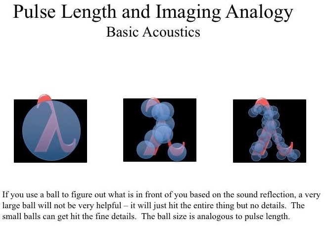
So how does the pulse length determine image resolution. Without complex mathematics, it is quite difficult to illustrate their relationship. However, hopefully with the illustration to the left will help you appreciate this.
Let's imagine we are in a pitch black cave. You want to know what is in front of you though you only have a ball in hand. So you decided to throw it in front of you and attempt to determine what is in front of you based on the sound that is reflected.
Let's imagine we are in a pitch black cave. You want to know what is in front of you though you only have a ball in hand. So you decided to throw it in front of you and attempt to determine what is in front of you based on the sound that is reflected.
Practical Point:
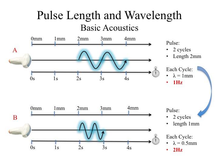
Given pulse length affects imaging, can we control this parameter? We can INDIRECTLY by changing the Frequency. The diagram on the left illustrates this.
Probe A emits a pulse consisting of 2 cycles and a pulse length of 2mm. Each cycle has a wavelength of 1mm and frequency of 1Hz. Suppose we want to reduce the pulse length, how can this be done?
Here, probe B emits a pulse consisting of 2 cycles, but with a pulse length of 1mm. This is achieved by increasing the frequency of each cycle to 2Hz resulting in a cycle wavelength of 0.5mm and, hence, a pulse wavelength of 1mm.
To further illustrate the determinants of wavelength (pulse or cycle), the equation on the left demonstrates it is proportional to Propagation Velocity and inversely proportional to Frequency.
Propagation velocity is how fast the US wave moves through tissue, which is very tissue dependent. You cannot control this.
Wave Frequency, on the other hand, can be controlled. Recall that each probe has a specific range of frequencies, and some machines allow you to select the frequency along that range. This you can control.

Not only does the transducer has the ability to emit an US pulse wave, it, also, has the function to listen for returning echoes.
When the emission function is On, a pulse wave will be generated. This is followed by a phase when the emission function is OFF for active listening for returning echoes. Both functions cannot exist simultaneously.
When the emission function is On, a pulse wave will be generated. This is followed by a phase when the emission function is OFF for active listening for returning echoes. Both functions cannot exist simultaneously.
Now, that we know there are these two phases, we are going to explore a concept called the Pulse Repetition Frequency and how it relates to the emitting and listening phase. This is important for understanding several US artifacts - particularly range ambiguity and doppler US.
3. Pulse Repetition Frequency and Imaging
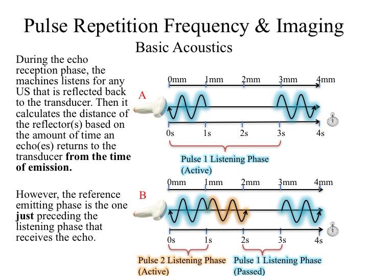
Let's illustrate why this is important with the diagram on the left. Probe A emitted a pulse (let's label it pulse 1) which reflected back during the active listening phase of pulse 1. The machine will then calculate the distance based on the total time the pulse has traveled referencing from the beginning of the emission phase.
However, what happens if the reflected wave returned after the active listening phase of pulse 1 like in Scenario B? If pulse 1 is received during the the active listening phase of pulse 2, the machine would think that the returning pulse originated from the emitting phase of pulse 2. It will calculate the distance in reference to the beginning of the emission phase of pulse 2.
This alternating phases of pulse emission and reception can be defined by the concepts of Pulse Repetition Frequency
and Pulse Repetition Period.
PRF: how often the transducer emitting a pulse
PRP: total duration of one emission + one listening phase
PRF and PRP are inversely related to each other.
PRF: how often the transducer emitting a pulse
PRP: total duration of one emission + one listening phase
PRF and PRP are inversely related to each other.
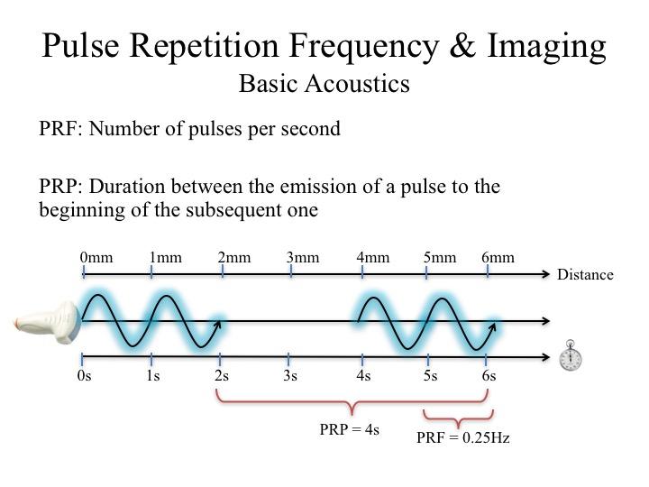
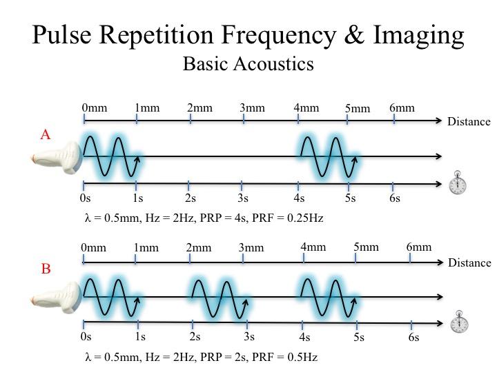
Here we have Scenario A and B, emitting pulses of the same characteristics. However, the difference is how often the probes emit a pulse wave and how long it spends listening for echoes.
In scenario A, the probe spends 1s emitting a pulse and 3s listening to echoes. This would yield a PRP of 4s. PRF = 1/(PRP) = 0.25s.
In scenario B, the probe spends 1s emitting a pulse and 1s listening to echoes. This would yield a PRP of 2s PRF = 1/(PRP) = 0.5s.
The smaller the PRF, the more time the probe spends in the listening phase. The larger the PRF, the less time the probe spends in the listening phase.
This video illustrates the importance of PRF/PRP with regards to image generation and placement (distance).
In the first scenario, pulse 1 was emitted, hits the smiley face, then the returning echo reached the probe during the active listening phase of pulse 1. Given that it took the pulse to 6s to travel to-&-fro, the smiley face is 3cm deep from the probe.
What if we increase the PRF (emitting the pulse more frequently but at the expense of active listening duration)? In the second scenario, pulse 1 was emitted and hits the smiley face, but it was received during the active listening phase of pulse 2. As a result, the machine thinks returned in 3s from pulse 2 emission. Hence, the smiley face is placed at 1.5cm instead. This error is an Artifact. The structure does exist, but just at the wrong place.
Take Home Messages:
- Pulse length affects resolution.
- You can change the pulse length by controlling the frequency.
- US has both a pulse emission phase and an echo reception phase.
- Both phases alternate, therefore they cannot coexist simultaneously.
- The US machine calculates the distance of the object by referencing to the most recent pulse emission phase.
- The relative duration and repetition of these phases are conveyed by the pulse repetition frequency and pulse repetition period.
- PRF/PRP can be a source of artifact.