
Thoracic Basics - Knobology and Imaging Technique
Knobology and Imaging Technique
2. Knobology Optimization
3. Image Acquisition
Thoracic PoCUS has its specific Image Acquisition finesses that are crucial to producing high quality images:
1. Probe Selection
2. Knobology Optimization
3. Image Acquisition
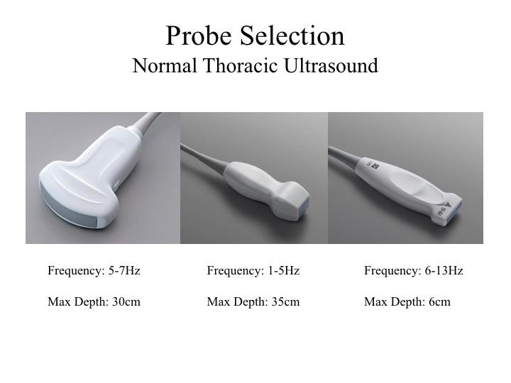
1. Probe Selection:
Each probe has its own profile best fit for specific thoracic PoCUS indications.
Curvlinear: Given its wide footprint, you can image multiple rib spaces at once; it can view the pleural line decently most of the time; and its allows deep imaging - useful for pleural effusion assessment.
Phased-array: It can fit into narrow rib space, and generates similar images as per the curvilinear. However, pleural line assessment is very poor.
Linear: Best for assessing superficial structures - yields high resolution images of the pleural line
2. Knobology - Optimal Settings:
The utility of thoracic PoCUS is dependent on generation of US artifacts. Any processor settings that attenuate artifact production should be OFF for this indication. (The exception is pleural effusion imaging which may result in quality degradation.)
At minimum, do turn off Tissue Harmonics and Multi-Beam (aka. Compound Imaging). Some newer machines have a preset "Lung" Mode whereby the knobology are optimized for thoracic PoCUS.
Exercise:
Try imaging the thorax (parenchyma, effusion) with different settings and observe what happens to the images

3. Image Acquisition - Where to scan?
There are several proposed methods to divide up the thorax into standardized zones. The major differences are the number and, hence, size of the zones scanned. The more you divide up the thorax, the more zones you will be scanning. The advantage is that it will be scrutinizing. However, it is more time consuming.
The thoracic partitioning method shown on the left is commonly used. Its origin stem from critical care patients who cannot sit up. Each hemithorax is divided into 4 zones demarcated by PSL (Paratsternal Line), AAL (Anterior Axillary Line), PAL (Posterior Axillary Line), and the 5th Intercostal Space.

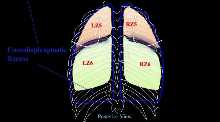
The schematic diagram correlates the partition method described above to the lobes of the lung.
Anteriorly:
Anteriorly:
- RZ1 = Right upper lobe (RUL)
- RZ2 = Right middle lobe (RML)
- LZ1 = Left upper lobe (LUL)
- LZ2 = Lingula (heart is usually in the way)
- RZ3 = RUL/RML - depends on the cut
- RZ4 = Right lower lobe (RLL) + costodiaphragmatic recess (CDR)
- LZ3 = LUL/LLL - depends on the cut
- LZ4 = Left lower lobe (LLL) + CDR

Posterior:
if the 5th intercostal space is extended all the way to the back, the posterior thorax can be further partitioned into Z5 and Z6. Have the patient self-hug to displace the scapula to expose Z5.
- RZ5 = RUL
- RZ6 = RLL + CDR
- LZ5 = LUL
- LZ6 = LLL + CDR
3. Image Acquisition - How to place the probe?
Note: the visceral and parietal pleura cannot be resolved into two separate structures by US. When they are apposed, they are seen as one line - hyperechoic pleural line.
- Place probe perpendicular to an intercostal space
- Indicator points towards the head
- Attain this image - termed "Bat Wing" composing of the structures in the schematic diagram
- UTMOST: render the US beam perpendicular to the PLEURA (not the chest wall) to generate thoracic US artifacts
Note: the visceral and parietal pleura cannot be resolved into two separate structures by US. When they are apposed, they are seen as one line - hyperechoic pleural line.

What happens if the probe is not perpendicular to the pleura?
This image shows what happens when the US beam is not perpendicular to the VPPI:
This image shows what happens when the US beam is not perpendicular to the VPPI:
- pleural line is less echoic and coarser
- A-line artifacts are attenuated or mitigated
- by far, anecdoctally, this is the most common problem with thoracic image acquisition
- you may notice that the probe is quite tilted in relation to the chest wall when the best image is acquired. However, in fact, the US beam is perpendicular to the VPPI.

A common question:
Why placing the probe perpendicular to two adjacent ribs is preferable to placing the probe parallel the intercostal space?
When the probe is placed parallel to the ICS, the fibers of the intercostal muscles are imaged along their long-axis - these muscles run along the ICS. When the patient breaths, especially during forceful respiration, the dynamic movements of these muscles will be captured. Given their proximity to the Pleural Line, it can make Pleural Sliding assessment more difficult - which one is moving?
If the probe is placed perpendicular to the two ribs, the US beam cuts the intercostal muscles in their short-axis, therefore their movements are not captured. Hence, Pleural Sliding interpretation will not be confounded. However, the parallel placement does allow one to evaluate more pleura at once.

Take Home Message:
- render the US beam perpendicular to the VPPI
- Try different angle of insonation to the thorax and see what happens to the image
- Try imaging the thorax perpendicular and parallel to the ICS