
Machinery and Knobology - Transducer
1. Transducer Components:
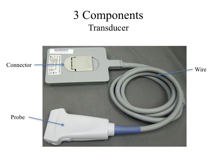
The transducer has three components:
The transducer has three components:
- Probe: the part that contacts the patient
- Connector: the module that connects the transducer with the US machine
- Wire: the cable consisting of many wires that bridges the probe and connector
The probe has to two components externally:
If you cannot finding the indicator, simply place your finger on one side of the footprint and correlate it with the corresponding side on the monitor.
- Footprint: the part that interface with the patient. This is where the US pulse waves are emitted and returning echoes are received. Depending on type of the probe, the dimensions, area, and the shape of the footprint differ.
- Indicator: refers to a landmark on the body of the probe that serves as a reference point to orientate the image on the monitor - which side of the probe corresponds to the side on the monitor. Depending on the brand and/or machine series, the indicator maybe a dot, linear groove, light, etc...
If you cannot finding the indicator, simply place your finger on one side of the footprint and correlate it with the corresponding side on the monitor.
2. Indicator
Let’s focus on the Indicator as beginners usually find the orientation of image on the screen relative to the orientation of the probe difficult to grasp. As mentioned earlier, the probe has an indicator, schematically shown in red here. On the screen of the monitory, there is a landmark that corresponds to side where the indicator is on the probe. On the TE7, it is a little “blue M”; and Sonosite M Turbo uses a little small green dot - as bracketed in the Red Square.
Let’s focus on the Indicator as beginners usually find the orientation of image on the screen relative to the orientation of the probe difficult to grasp. As mentioned earlier, the probe has an indicator, schematically shown in red here. On the screen of the monitory, there is a landmark that corresponds to side where the indicator is on the probe. On the TE7, it is a little “blue M”; and Sonosite M Turbo uses a little small green dot - as bracketed in the Red Square.
Take a look at schematic diagram on the left. For US machine 1, the indicator points towards the shorter (red) side of the trapezoid. Hence, this shorter side will be on the same side as the indicator on the screen.
If we rotate the probe by 180 degrees such that the indicator on the probe corresponds to the the longer (yellow) side of the trapezoid, it will be reflected on the screen, respectively, per US machine 2.
The indicator symbol on the screen differs for each machine - enveloped in red squares on the far right.

3. Footprint
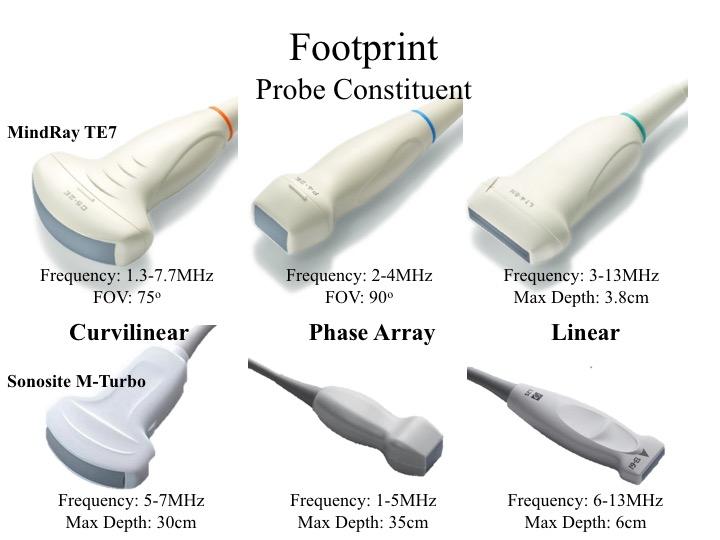
Here is a selection of probes for the MindRay TE7 and the Sonosite M-Turbo. The three footprints that are most commonly utilized by Internal Medicine:
Each has its own Field of View and Range of Frequencies.
Here is a selection of probes for the MindRay TE7 and the Sonosite M-Turbo. The three footprints that are most commonly utilized by Internal Medicine:
- Curivilinear (aka. Abdominal) probe: footprint is curved and wide
- Phased array (aka. Cardiac) probe: rectangular shaped footprint for wedging between rib space
- Linear (aka. Vascular) probe: footprint is flat and in the shape of a line
Each has its own Field of View and Range of Frequencies.
4. Field of View
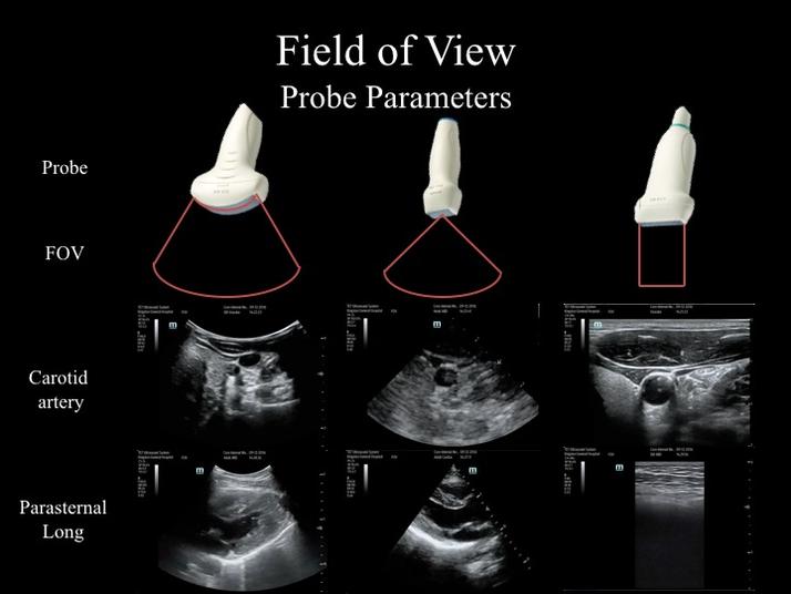
The Field of View is essentially the field of vision that the probe can exhibit on the monitor. Here, the FOV of the three probes are tabulated for you schematically and, also, in situ.
Notice both curvilinear and phased array both have wide FOV though the latter has a point-blank base. Whereas the linear's FOV is defined by parallel perpendicular lines in the shape of a square/rectangle.
If you image the carotid and heart, these are the images you will attain with respect to their FOV.
Practical Point:
You can almost image anything with any probe depending what image you are trying to acquire. Usually one probe is most ideal though suppose you have no access to it, adapt with the other probes if possible
5. Frequency
Another important performance parameter of a probe is the Frequency of the pulse waves it is capable of emitting. The probes, nowadays, are able to emit a range of frequencies - called the Bandwidth.
For simplicity sake, the practical importance of Frequency is tabulated here for you.
Practical Point:
- If you want to image a deep structure, use lower range frequencies
- If you want to image a superficial structure, use higher frequencies
- If you want to have better image resolution (spatial - not temporal), you would want higher frequencies

Take Home Message:
- The indicator on the probe corresponds to a landmark on the monitor to image orientation
- Each probe has its own Bandwidth of frequencies
- The higher the frequency, the higher the resolution though sacrificing depth penetration
- The lower the frequency, the deeper the pulse wave can penetrate and return though at the expense of image resolution