
Artifacts - Added Information
Added Information
This type of artifact is characterized by extra information displayed on the monitor in comparison to the true anatomical correlated. Simply put, there are things on the screen that should not be there.
Four Two Subtypes will be discussed:
1. Volume Averaging
2. Mirror Artifact
3. Speckle Artifact
4. Reverberation Artifact
Four Two Subtypes will be discussed:
1. Volume Averaging
2. Mirror Artifact
3. Speckle Artifact
4. Reverberation Artifact
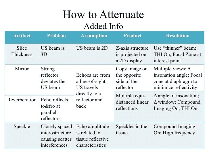
1. Volume Averaging (aka. Elevation resolution artifact, Slice Thickness artifact).
This artifact stems from the assumption that US beam is 2D - XY axis. As you recall, it has a Z-axis - 3D.
When a strong reflector is in the Z-axis, the echoes from this structure will be processed. Given that the processor assumes that the US beam is only 2D, any signal processed will be plotted on the XY-axis only. Hence, the object in the Z-axis will be displayed in the XY plane (ie. Smiley is off the main axis, but projected onto the monitor and blurring Heart).
Attenuate/Mitigate by placing the Focal Zone (narrowest beam profile including Z-axis) at the interest point.
For simplicity, the above diagram displayed the US beam profile as a pyramid to illustrate the Z-axis and what happens when there is a strong reflector in this dimension.
However, the beam profile, as you know, is more complex than that as per this animation. We can take advantage of its shape to mitigate this artifact. Notice the Focal Zone is the narrowest - shortest XYZ dimensions.
By placing the Focal Zone at the point of interest, one will attenuate/mitigate slice thickness artifact - at least at the region that you are concerned about. There maybe volume averaging present distal or proximal to focal zone, but they do not contain the structure you are interested in..
2. Mirror Artifact:
when an object is present on one side of a strong reflector is, also, displayed at an equi-distanced on the other side of the reflector. This is most commonly seen at the diaphragm - a specular reflector.
This arises because the processor assumes the US beam travels in a straight line.
This animation shows the pathways of sound waves when an object is near a specular surface resulting in a mirror image.
Attenuate/Mitigate: Change angle of insonation; Adjust focal zone at the level of the diaphragm to minimize its reflectivity; Multiple views
3. Reverberation Artifact:
characterized linear reflections of the reflector that are equally spaced
This is artifact is generated when highly reflective surfaces are parallel to each other. The echos generated from a primary US beam will be repeatedly reflected back and forth before returning to the transmitter for processing.
Attenuation/Mitigation: render the insonation angle less perpendicular to the reflective surfaces; an alternate window
4. Speckle Artifact:
characterized by a random granular texture. This is usually seen in solid organs like the liver and kidney as imaged in adjacent image.
Speckle results from scatter interference pattern from echoes generated by closely spaced microstructures that are too small to resolve. However, the scattered waves interfere constructively and destructively resulting in bright and dark granular spots (see the far left pictures illustrating wave inteferance patterns).
Attenuation/Mitgation: High-frequency, Multi-beam, Harmonics

This summarizes artifacts characterized by added information to the image in comparison to the anatomical correlate and how to attenuate/mitigate them if needed.
Take
Home Messages:
- Reverberation artifact is commonly encountered particularly for thoracic ultrasound - A-lines
- Mirror artifact is seen usually seen at regions near specular surfaces - most commonly seen when imaging thoracic zone 4 near the diaphragm - we take advantage of this artifact to inform us whether a pleural effusion is present, or not
- As you can see, sometimes, artifacts are diagnostically useful - attenuate them accordingly